HST’s software targets the design of ground mount systems with Medium Voltage (MV) or High Voltage (HV) interconnections. As such, some general assumptions are made regarding the electrical equipment used and the configurations in which it is connected.
PV Modules are connected in series to form strings. The number of modules per string is determined automatically. Multiple strings are paralleled into combiner boxes (central inverter systems) or string inverters (string inverter systems). The number of strings paralleled into each combiner box or string inverter is determined automatically. The maximum number of combiner box inputs may be set by the user. Additionally, multiple strings may be “pre-paralleled” into a single combiner box or string inverter input depending on the string characteristics. This is particularly useful for thin film modules which have relatively low module current compared to mono or poly-crystalline modules. HST software allows up to 10 strings to be pre-paralleled into a single combiner box input and determines this automatically. When strings are pre-paralleled, positive and negative string wiring harnesses and in-line fusing for each string are included in the BOM.
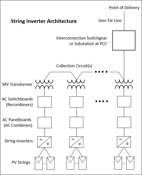
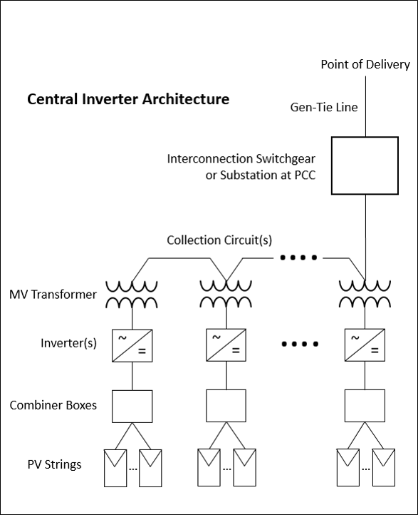
Central or String inverters may be used within the design and this significantly affects how the electrical balance of system is designed. Where central inverters are specified, combiner boxes are used and up to 4 central inverters may be located at a single inverter station. The number of inverters per station is user-configurable. Where string inverters are specified, rack-mounted panelboards (AC combiners) and pad-mounted switchboards (AC Recombiners) are used within the design. Panelboards and string inverters are installed within the array and switchboards are pad-mounted and road accessible.
Additionally, pad-mounted, step-up transformers are included at each inverter station (central inverter designs) or switchboard station (string inverter designs), one per station. The transformers are considered to be loop-fed transformers that are connected in a daisy-chain pattern to form a collection circuit. Multiple collection circuits may exist within a single project design. The number of inverter stations per collection circuit is determined automatically during site layout.
All collection circuits terminate at the Point of Common Coupling (PCC). The location of the PCC is specified by the user and is most typically the location of the interconnection switchgear for medium voltage interconnections or the project substation for high voltage interconnections. The PCC is also the location where a Generator Step-Up (GSU) transformer will be modeled if the system is interconnected at a high voltage.
Finally, it is possible to model the effects of a Gen-Tie line between the PCC and Point of Delivery (POD) if these two locations are not coincident. While the routing and location of the gen-tie line are not physically modeled, the distance of the gen-tie line can be specified by the user so that the losses associated with the gen-tie may be included in the energy modeling.
Note: Different definitions for medium and high voltage exist. HST assumes all voltages above 34.5kV are considered high voltage and therefore require an additional GSU step-up transformer at the PCC.
A high-level single line of a central inverter design is shown below:
A high-level single line of a string inverter design is shown below: